Westinghouse, along with Mitsubishi Heavy Industries, collaborated to develop and launch the 501F gas turbine in the early 1990s. Since then, this has grown to be a very well-liked choice for power production applications all around the world.
In the early stages of a unit’s life, most users resort to the original equipment manufacturer, or OEM. Especially when it comes to an overhaul, along with maintenance assistance. But, as their assets age, an increasing proportion are using specialized independent suppliers to perform these services.
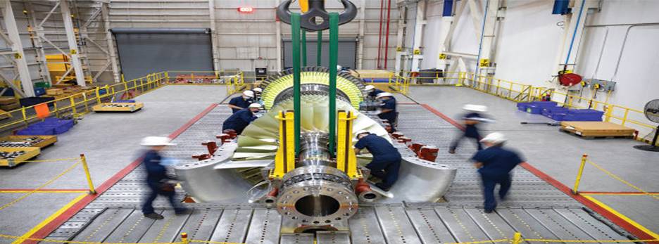
Any maintenance provider must meet certain requirements due to the weight and dimensions of a big turbine. A huge overhaul facility should be equipped with huge, highly specialized machinery.
This is needed for disassembly, inspection, repair, balancing, and reassembly. These facilities feature a vertical pit as well as a scissor lift. Especially when it comes to a Mitsubishi 501F rotor stacking or unstacking, in addition to a big capacity crane.
Increasing gas Dependability
- The customer’s needs and the equipment’s operating history. These dictate the extent of the overhaul work on a machine as big and complicated as the 501F. A service will usually start with the complete rotor unit being disassembled and inspected. And then cleaning, non-destructive testing (NDT), and life-cycle evaluation.
- Significant technical work is frequently needed to find and execute an efficient remedy. That’s when problems are discovered during the inspection process or operation.
For instance, when a machine showed noticeable vibration, it was turned off and sent to a servicing facility. High radial run-out of about 0.18 inches was found during inspection. The register that fit around the forward stub was discovered to have entirely broken off during disassembly.
- Failure as well as wear of the anti-rotation hinges holding the air baffles in place is another frequent problem. The turbine is severely damaged because of the failures. This will cause the baffles to stress, wear, and sometimes break away entirely.
Air baffles having anti-rotation characteristics can alter the turbine’s anti-rotation slots to suit them. Thus, preventing this problem from happening again. Either an alternative baffle design that can be placed in the field or the rotor removed can be used for this job.
- When the compressor bolt-on fails at the front end. The released fastener might flow through the machine and do serious damage. It also affects the safety of workers. Go to https://www.insurancejournal.com/news/southcentral/2012/06/19/252142.htm for an example.
The problem is most likely caused by pressure on the fastener’s last complete thread. And an inadequately loaded surface region between the fastener along with hub to reduce movement.
That’s according to the analysis of the defective components. This makes it possible for the chip at the bolt’s end to spread while it is in use.
- Issues with cooling air flow are frequently the root of vane failure. This may lead to inadequate flow through the pinhole channels that lead to the trailing edge. Or the removal of the essential air dam at the vane’s leading edge.
- Several sophisticated repair techniques can provide users with substantial financial advantages for vanes. The “coupon” repair method enables the damaged portion of the blade to be cut out. And a new segment brazed into place instead of replacing the complete vane.
The vane is put back into operation after cooling holes have been cut into the new sections. Then, following grinding, testing, and surface treatment.
- In other cases, a slump brazing procedure might be performed to add more material. That’s if an examination shows that a vane’s highly curved sections have grown too thin for continuing usage. This procedure prolongs the vanes’ useful life and provides an affordable repair with little downtime.
- In the end, gas turbine operators and their insurers are worried about how long their rotors will last. The best course of action, according to user groups, experts, and OEMs, is to properly check components. Also, assess the risks and put mitigation measures in place.
Rotor Inspection And Upgrades
After 12 years of operation, whichever comes first. Mitsubishi Power suggests a comprehensive rotor inspection, or CRI. You can find here other Mitsubishi Power developments.
The rotor must be completely disassembled, necessitating a shop visit. To ensure that performance and reliability objectives are met. Every component is subjected to a thorough nondestructive inspection. Repairs, replacements, and modifications/upgrades are carried out as needed.
During a CRI, the following crucial component inspections are carried out:
- Spindle bolts, for fretting or fatigue brought on by low-speed use and long turning-gear hours.
- For cracking, use a torque tube.
- Turbine-disc cooling-air channels, for blockages caused by foreign objects, rotor rust, and cooling-air piping.
- Turbine-disc blade grooves, for stress and wear brought on by pitting corrosion, blade rock, etc.
- The curvic clutch, which contributes to the relative motion between neighboring discs due to wear from prolonged use of the gear. Since this turns and/or through-bolt relaxation.
- Compressor and discs, for corrosion, cracking, pitting, creep, and/or hardness changes. These are caused by prolonged exposure to corrosive elements, high working hours or starts, and unusual operating circumstances.
- Shaft journals for wear, scoring, and/or cracking caused by electrolysis. Also, excessive working hours, inadequate oil filtering, and/or lubricating oil loss.